Please select your location and preferred language where available.
A 56-Gb/s PAM4 Transceiver with False-Lock-Aware Locking Scheme for Mueller-Müller CDR
November 30, 2022
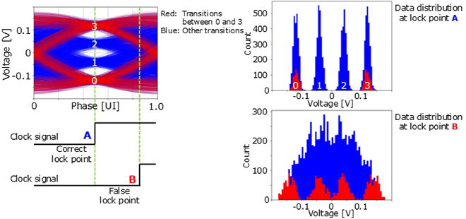
Recently, PAM4*1 signaling has been used instead of conventional NRZ*2 signaling to meet the demand for high-speed data communications. In addition, an ADC*3-DSP*4 based receiver has also been used instead of an analog-based receiver for enabling digital equalization to handle high insertion loss channel with high data rate. Most ADC-DSP based receivers use baud-rate*5 CDR*6 such as Mueller-Müller CDR, while most analog-based receivers use the 2x oversampling CDR. However, in the conventional baud-rate CDR circuits, the clock signal is occasionally locked at false-lock points as a result of misjudging specific transitions between data 0 and 3 as whole transitions of the PAM-4 signaling (Figure 1).

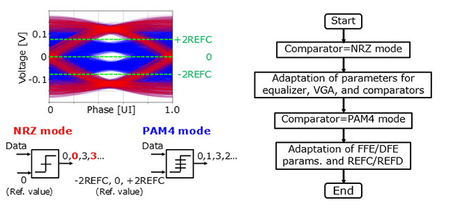
We discovered that the clock signal is locked at the correct point when the comparator for the CDR is operated in the NRZ mode even if the PAM4 signaling is input. Therefore, the false–lock points can be avoided by using the comparator for the CDR in the NRZ mode (Figure 2). The comparator for the CDR is first operated in the NRZ mode and then the parameters of the equalizers, variable-gain amplifiers, and the comparators for the CDR and data-path are adaptively controlled. Next, the clock signal is successfully recovered from the PAM4 input signal. After that, the comparator for the CDR is changed to the PAM4 mode and the parameters of the equalizers and comparators are optimized again and the clock signal is adjusted properly.

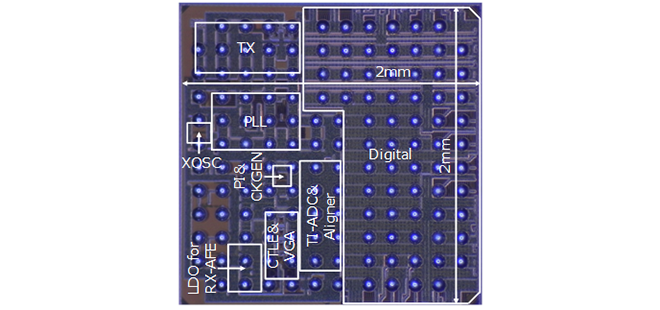
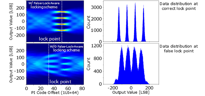
The die micrograph of the fabricated chip is shown in Figure 3. The chip is fabricated in a 16-nm FinFET process. When measuring the fabricated receiver, 56-Gb/s PAM4 signaling is generated in the transmitter and then input into the receiver via an external cable. By using the proposed false-lock-aware locking technique, the PAM4 signaling is correctly received even when the clock signal is locked at the false-lock point initially (Figure 4).


- PAM4 (4-level Pulse Amplitude Modulation): Data transmission technique using four voltage levels representing two-bit data. Although one symbol contains one-bit data by using NRZ, one symbol contains two-bits data by using PAM4.
- NRZ (Non Return to Zero): Data transmission technique using two voltage levels representing “0“ and “1”.
- ADC (Analog-to-Digital Converter): A Circuit that converts an analog signal to a digital signal.
- DSP (Digital Signal Processing): The processing of a digital signal.
- baud-rate: Number of symbol changes per one second.
- CDR (Clock and Data Recovery): Technique recovering clock and data signals from received signals.
This research has been presented at ESSCIRC (European Solid-State Circuits Conference) in September 2022[1].
This development is based on a project commissioned by the New Energy and Industrial Technology Development Organization (NEDO).
This article is reconstructed from excerpts of references [1] @IEEE 2022.
Reference
[1] F. Tachibana et al., “A 56-Gb/s PAM4 Transceiver with False-Lock-Aware Locking Scheme for Mueller-Müller CDR,” in Proceedings of IEEE European Solid-state Circuits Conference (ESSCIRC), pp. 505-508, Sep. 2022.

